Technical Issues - Layer Error AnalyzerLet's assume that you have developed
reliable inverse-synthesis techniques which
let you correct optical coating designs. If you can show that there are
systematic thickness-dependent variations, you should be able to modify new
designs and thereby achieve higher coating yields.
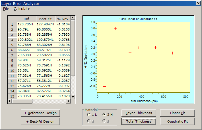
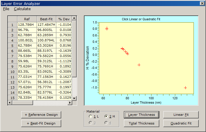
Click + Reference Design to clear the grid and add the theoretical coating design and + Best Fit Design to insert the reverse-engineered (inverse-synthesis) design. Then select the material you are interested in and click either Layer Thickness (monitor corrections depending on thickness of each layer) or Total Thickness (tooling factor corrections depending on total thickness of each layer). You can choose to plot % Deviation (centered about 0.0) or Correction Factor (centered about 1.0). As shown above there is a poor correlation with Total Thickness, but as can shown below there is an excellent correlation with individual Layer Thickness.
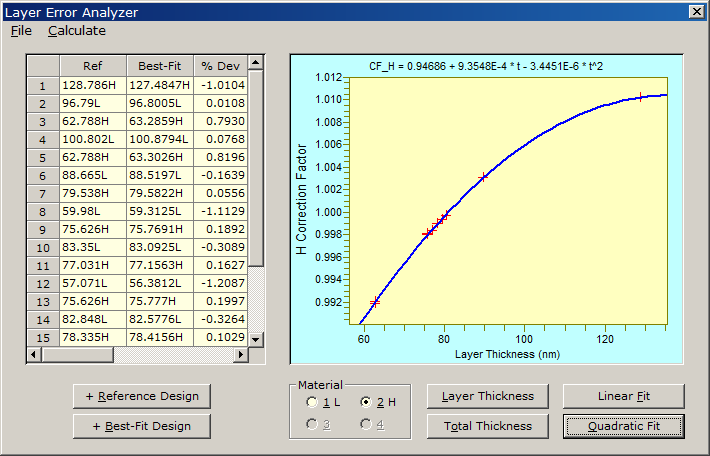
Switch to Correction Factor mode (Calculate Menu) and then click Quadratic Fit to determine a functional relationship. This can be seen below.
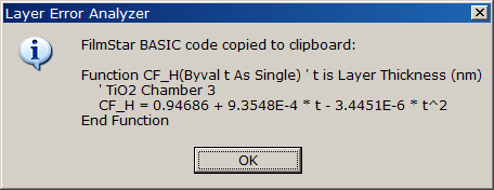
The remaining task is to apply the correction factors. WE DON'T REALLY WANT TO MODIFY THE DESIGN! What we want to modify are the thickness settings transferred to the coating chamber. Such modifications can be implemented in FilmStar BASIC in DESIGN (ThickList.bas, Maxtek DCM-220.bas), CRYSTAL, or MONITOR. What is needed in all cases is a Correction Factor function. Click Create BASIC Code in the Calculate Menu in order to generate the following:
Disclaimer...No claim is made that these are the only possible systematic errors. We look forward to extending and modifying the Layer Error Analyzer according to users' experiences.
Interestingly a Corrected Design gives a spectrum which is essentially a mirror image of the design with errors. This is most clearly illustrated by the flat laser output coupler. |
Copyright © 2023 FTG Software Associates
Last updated on
January 31, 2023