|
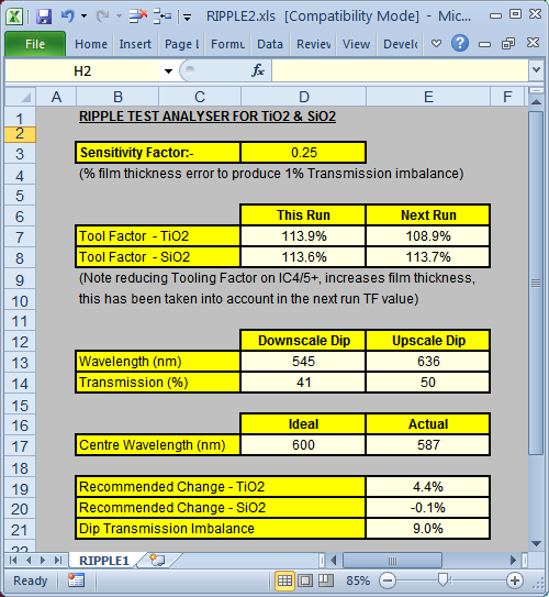
Technical Issues - Tooling Factor Correction Optical monitor tooling
(monitor/substrate M/S) can be calculated in MONITOR. One deposits a
fairly thick film, say 15 quarter waves, on a monitor glass and
subsequently measures the coated substrate in a spectrophotometer. In
former times a slide rule helped to determine the number of quarter
waves on the coated substrate. This technique, possibly developed at
Bausch & Lomb in Rochester, has stood the test of time and is widely utilized. Is the half
wave ripple design optimum for DESIGN tooling correction? How much can
thicknesses deviate before tooling correction fails? We applied our
Gedankenspektrum
technique with a FilmStar BASIC program simulating tooling deviations
from -30% to +30%. As it happens, the half wave ripple design is not
the best candidate. In initial experiments we found 1H 1L 2H 1L
1H to be somewhat superior with correct solutions for ~20% deviation in both H
and L layers.
The FilmStar BASIC program and corresponding FILM Archive file can be downloaded. As shown below, solutions are possible with fairly large thickness deviations.
|
Copyright © 2023 FTG Software Associates
Last updated on
January 31, 2023


